The Challenge
Due to capacity limitations with their existing batch production system, a pharmaceutical company was supply limited and unable to expand to keep up with growing demand.
The Solution
The company selected Applied Control Engineering (ACE) to design and configure a control system for two identical batch production lines consisting of process and clean-in-place (CIP) skids that can be dynamically controlled and configured, allowing for a significant increase in production. Since the initial system was developed, ACE has designed and deployed three additional systems for this company.
Initial System Implementation
Throughout the course of the last several years ACE has been contracted to develop four separate iterations of a batch control system as this company continues to expand production. The initial project we were hired for involved batch control for two identical 45L production lines, each consisting of a process skid, interchangeable CIP skids, and shared skid-based resources such as a reverse osmosis deionization (RO/DI) systems and steam. The new control system we installed was based on the ArchestrA system platform with two redundant Rockwell ControlLogix L74 processors with three remote racks of I/O setup in a device level ring. The ArchestrA platform also included a batch server, a historian server, a Galaxy repository, and an information server.
This initial system consisted of seven control modules for the process which covered 95 percent of the control equipment. For each of these modules, specification and test documents were generated. The remainder of the equipment was controlled via sequences or special programming which was documented in functional requirements and software design specifications. Phase logic was implemented for CIP, sterilization-in-place (SIP), and process control with modular batch recipes defining the execution of the phases.
For this system, we configured thin clients in two different form factors – a wireless touchpad for mobile users and wired client devices for area operations. Each client was paired with a dedicated virtual machine that ran on one of the two VMWare Hypervisor servers. The operator interface incorporates navigation, trending, batch management, and almost 70 process graphics.
In addition to the conventional rack-based I/O, this configuration also included devices on Foundation Fieldbus and DeviceNet as well as wireless Rosemount transmitters on each of the tanks. The control system configuration also used equipment-level add-on instructions (AOIs) that were mirrored in the system platform configuration.
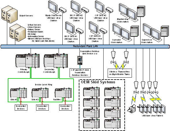
A diagram of the original system.
Further Expanding Production with Additional, and Larger, Batch Systems
After the success of this initial system, ACE was contracted for a second phase that involved building an identical system for a contract manufacturer at a facility in the UK. Once this phase was complete, the company then decided it needed to scale production nearly 4x by building a 200L system in the same facility. With this new larger third phase system, ~1,600 I/O points were needed, and because of the size of the system, we knew the CIP and some of the other process steps would need to be completely redesigned to work at this new scale.
More specifically, for the CIP process in this phase 3 system, there were now two floors between the CIP and the rest of the equipment. And, with the filtering process in this new system, four banks of filters were needed instead of one, which meant we needed to make a number of changes to the process and the way the system was cleaned between batches.
Initially, we were developing the design for this new larger system based on the existing 45L process, but we also realized we needed to work closely with the company’s process engineers to ensure we were developing the right design to sequence the different devices needed for this larger system. For example, we spent a significant amount of time communicating with the customer to refine the equipment model and recipe design to allow portions of the system to be cleaned as soon as possible to optimize overall cycle time.
This resulting system included two trains that provided the ability to begin cleaning operations on the front-half of the system while the previous batch completed on the back half of the system. To successfully do this, we developed dynamic pathing in the batch manager that selects the appropriate path based on which set of filters are being used/cleaned and what is available. Once a batch is finished, the final tank is taken to a tank farm where properties can be adjusted prior to going to a filling line. The system was programmed using AVEVA System Platform for the HMI; AVEVA Batch Management for batch management; Rockwell Studio 5000 for the phase logic, control modules, and I/O; and SQL Server Reporting Services for reporting.
Throughout these different projects, we also made changes to improve performance. For example, in the first 45L system, we used a single PLC to process all the logic. To improve performance when we developed the phase 2 system, we used five PLCs. Additionally, after the first project, the client experienced some issues with scan times and performance of the HMI with Suite C. To address these issues, in the third project we upgraded to a Rockwell ControlLogix L85 controller and used a single processor. By doing this, the custom saw a 10-15x performance improvement as scan times were reduced from ~100 – 150 ms to 10 – 15 ms. Making this controller change did necessitate custom changes to the base code for the equipment phases, which was time consuming for this third phase. However, for the fourth phase that we are working on now, we were able to copy the code we already developed during the third project.
For communications, after the first system we started using only Ethernet IP as the protocol, eliminating Foundation Fieldbus and DeviceNet communications. We also did not use wireless transmitters after the first system. Instead, we used connectors with unique pin layouts that, when plugged in when a vessel was docked, identify who is using the system to make sure the right tanks show up in the right locations on the HMI.
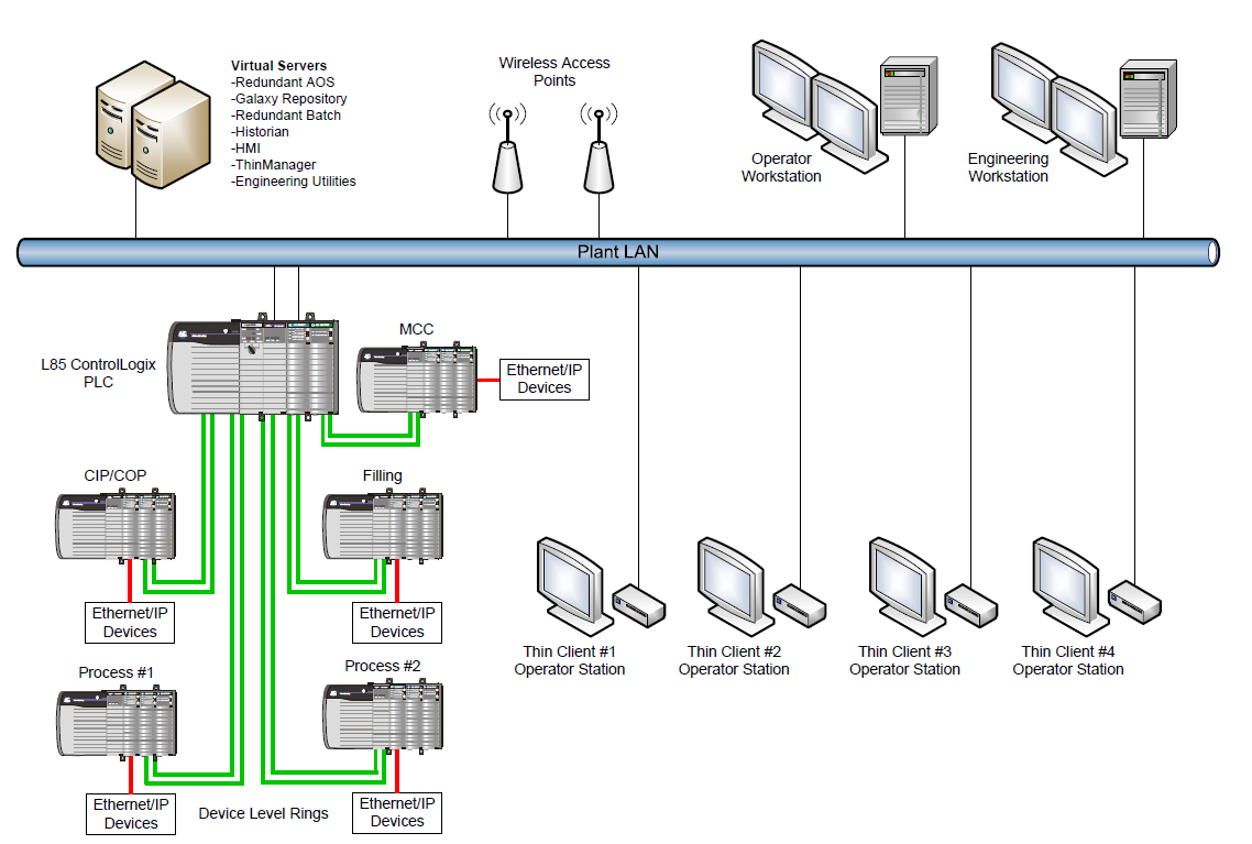
A diagram of the updated system.
Providing Ongoing Improvements and Support
Throughout the development of all these systems, ACE always provided the client with the appropriate support. For example, during the commissioning of the phase 3 system, we had two engineers onsite for nearly nine months supporting the startup. Today, we continue to support the UK facility with both normal and emergency support while we are working to commission the fourth system at the original US facility.
Learn more about our batch control expertise
