4 min read
Over the last century, electric motors have become ubiquitous for powering a variety of industrial devices including pumps, fans, and compressors. In the last few decades, variable frequency drives (VFDs) have emerged as a powerful, and now common, tool for reducing energy consumption and optimizing control of electric motors.
 If you work in industrial automation, you probably have VFDs installed on your electric motors and know the basics of configuring a VFD. When setting up your VFDs, you likely worked with your electrical contractor to ensure each VFD was adequately controlling its respective motor during commissioning. That said, electrical contractors are typically not experts in optimizing the drive to your specific motor and application needs. Most modern VFDs are complex control devices that include many parameters that, when fully understood, can be fine-tuned to bring even more benefits to your application.
In this two-part blog series, we will look at eight VFD parameters that are usually not addressed during installation and often can be optimized to bring a number of improvements to your motors. For all the settings discussed in this series, first verify with manufacturer documentation that the parameter matches what is listed herein, paying particular attention to engineering units.
Parameter 1: Thermal Current
The thermal current is a parameter that indicates the maximum allowable current, which is different than full load amps (FLA). While FLA is the rated power and indicates the maximum amps allowable for the motor long term, thermal current indicates a higher amperage that can be applied briefly, allowing the VFD to safely apply more than the motor’s standard rated power. The thermal current setting informs the VFD how much “extra” power the motor can handle and still operate without a thermal failure. When this limit is exceeded, the VFD can trigger a fault before a motor overload occurs, protecting the motor from thermal failure. When configuring the drive parameter for motor current, you can find the FLA and motor service factor (SF) on the motor nameplate. Multiply these two values to calculate your thermal current in amps.
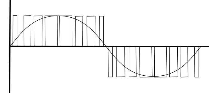
Parameter 2: Pulse-Width Modulation
Every VFD powering an AC motor works by converting line AC power to DC, which the VFD then modulates into an AC waveform. This modulation is done by rapidly pulsing the DC power – turning it on and off – to create an AC wave. The VFD adjusts the wave’s amplitude and frequency to spin the motor at the desired speed. The pulse-width modulation (PWM) switching frequency parameter regulates these pulses and can be adjusted by changing the number of pulses used to create the AC that powers the motor.
When PWM is not optimized for the motor and application, the dissipation of the heat produced by the motor and the drive is not balanced. If the PWM is too low, the motor will heat up faster, which is indicated by the motor screeching – often loudly. Eventually, this can lead to issues with insulation breakdown and/or bearing pitting. A high PWM requires the drive to work harder, eventually overheating the drive and shortening its life. An elevated PWM can also increase the development of reflective waves between the motor and the drive, which can cause increased current induction in the motor shaft, resulting in bearing pitting in the motor and grounding faults in the drive. By correctly fine-tuning the PWM, you can balance heat displacement and extend the life of both the motor and the drive
Parameter 3: Deceleration Time
Deceleration time is the parameter that determines how long the VFD will take to slow down the motor. A longer deceleration time will lead to a longer ramp down to fully stop the motor. While many installers know to optimize acceleration time to prevent issues with over-current at start-up, the deceleration time tends to get overlooked.
Adjusting the deceleration time is important for preventing an over-voltage fault that can be created when power is removed from a motor and the inertia from the load continues to spin the motor. This rotation causes the motor to generate electricity, which is fed back into the drive, causing it to fault. In this case, an appropriate deceleration time will decrease the magnitude of electricity created by the slowing load and prevent a fault. For example, if you have a motor controlling a fan and it takes 10 seconds to decelerate and stop the fan, you should, program your drive with this deceleration time to extend the life of your motor. Please note though, if a quick stop is required for process or safety reasons, additional hardware may be required and the appropriate process and/or safety experts, such as Applied Control Engineering (ACE), should be consulted.
Parameter 4: Minimum Operating Speed
Quite simply, the minimum operating speed is a speed setpoint, typically calculated as a percentage of maximum speed, below which the VFD will simply tell the motor to not run. Since most motors are cooled by an internal fan, which has a speed directly correlating with the motor speed, setting a minimum operating speed is important to prevent motor overheating that can occur at low speeds. For example, if the minimum operating speed is set to 10 percent, and someone provides a speed reference to the VFD of 5 percent, the VFD will not rotate the motor. Keep in mind that your controls integrator should make sure this is taken into account in the implementation of any interfacing PLC configurations such as PID algorithms where the drive is controlled by the control variable (CV).
In part two of this series, we explore how to continue to increase motor efficiency by optimizing your VFDs for frequency jump, motor control parameters, the graphical interface settings, and some manufacturer-specific parameters. To learn more about all the control and automation services ACE has to offer check out our services page.
Related Posts
ISPE Boston Area Chapter Product Show
On September 26, 2018, ACE joined the Boston Area Chapter of the International Society for...
Keep Your Critical OT Infrastructure Secure with Proper Patching
Patching is a critical line of defense in protecting OT assets from cyber threats. Simply put,...
Working with OMAC to Develop Industry Best Practices for Remote Access Security
In the past decade or so, many organizations have incorporated network connectivity into their...