4 min read
Laying the foundation for a control system that is easy to maintain, support, and upgrade starts long before equipment is purchased and installed. A key piece of this is developing a systematic approach to naming all your equipment – from your instrumentation to your programmable logic controllers (PLCs) –to provide consistency between your pipping and instrumentation diagrams (P&IDs), plant floor equipment, and human-machine interfaces (HMIs).
THEN…
This was difficult when PLCs first came on the scene because the addressing was register-based, meaning any data about the PLC was stored in numbered locations (sometimes with some letters mixed in) and the PLC tags were generally identified using the address of the register (e.g. N7:0 or 40100) Even though the register address could be assigned a symbol (or alias) and a description, these fields were not often used consistently during the development of new system. Worse yet, the data in these fields was not stored with the PLC configuration, so if the original file was lost, so was the information. This also contributed to the disuse of these fields. This could make troubleshooting a legacy PLC very difficult.
NOW…
Modern PLCs allow programmers to create variables as an alphanumeric string rather than use register addresses. This opens up numerous possibilities for how to name items within a control system to make them easier to identify. Some organizations chose the path of developing names that were very descriptive, like WaterTank1Level. This is certainly descriptive, but this type of identification has its drawbacks. The variable names are not of a fixed length, sometimes with a wide variation in tag count. This can make it difficult to incorporate that variable text into an object on an HMI screen or a faceplate. Also, what happens if the tank is repurposed to handle something besides water? Or another level is added? Moreover, as a system like this evolves and new programmers or technicians are involved, new features or functions may not use the same conventions as the original programmer. While this is an improvement from register addressing, if this naming convention is still at risk for obsolescence and retains some maintenance and troubleshooting challenges.
In most plants, an instrument is named in four locations, the HMI, the PLC, the instrument tag, and in design documentation such as P&ID's. It is ideal if these names align with each other. This is what a standardized naming convention based on the ISA 5.1 standard could offer your organization.
Bringing the ISA 5.1 Naming Convention to Your PLCs
When creating P&IDs today, it is commonplace for most companies to use the ISA 5.1 standard, which establishes a uniform method consisting of identification codes and symbols to designate the instruments and instrumentation systems used in any measurement or control system. An example of how this would look on a P&ID is shown in Figure 1.
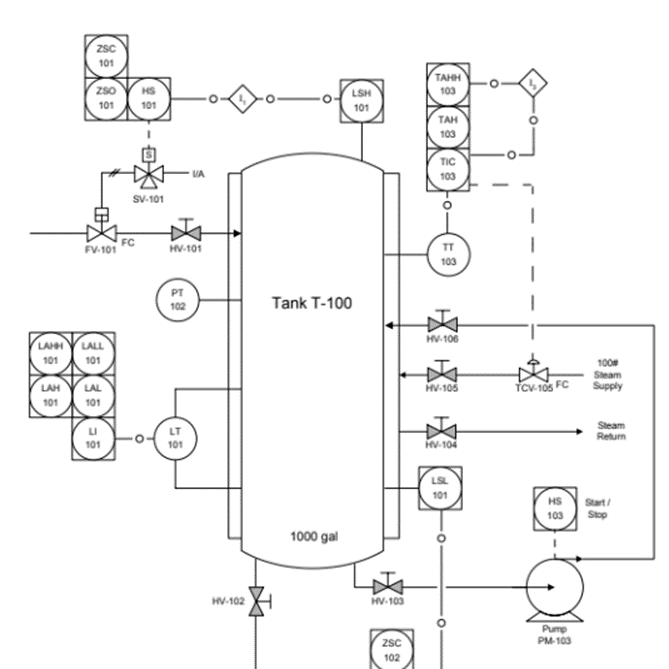
Figure 1. An example of a P&ID for a jacketed tank with level control.
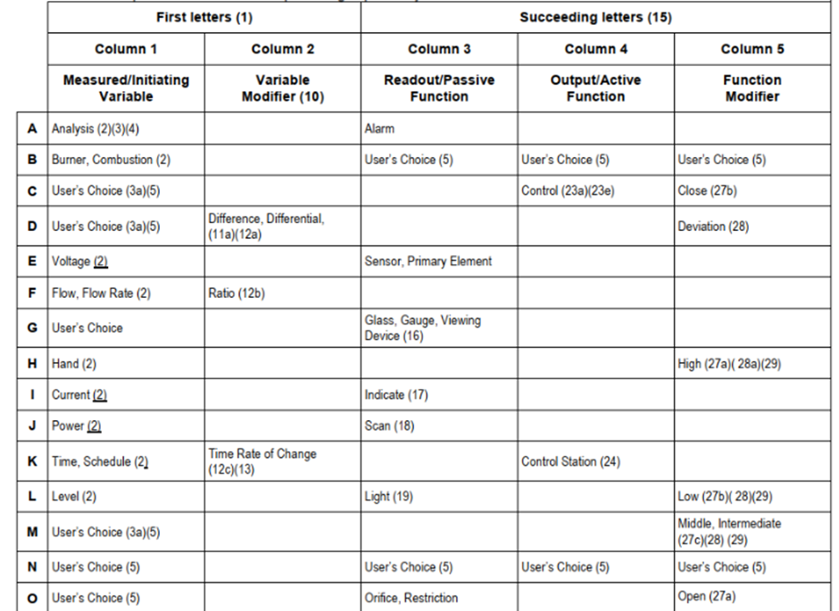
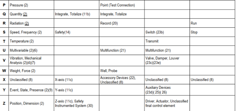
If you are not completely familiar with how this naming convention works, Table 1 shows how to establish the first part, or the alpha portion, of this naming convention.
While the alpha portion of the naming convention indicates the type of instrument, the numeric code identifies the loop number. The same loop number is generally assigned to all instruments and devices used to provide a function. For example, if you have a flow indicator, and based on the reading of that indicator you manipulate a flow control valve, both should be labeled with the same loop number.
If the control loop requires more than one valve, such as one valve that adds pressure and one valve that vents pressure, after the loop number, you should add a suffix to uniquely identify each valve. The pressurizing valve could be the “a valve” and the venting valve could be the “b valve,” which could result in function block names that read as PV-102a and PV-102b in this example.
The Advantages of Using a Standardized PLC Naming Convention
Establishing ISA 5.1 as your name convention throughout your project lifecycle starting from the original design documents to PLC variable and function blocks, and finally through to the HMI offers several advantages for your organization:
Implementation: The HMI and operator interfaces can use standard fields to display the variable names of the field devices since the length of those tags is defined under a convention
Simplicity: It is easier for everyone to understand the functions within a configuration, which can also be helpful for troubleshooting problems and training new employees.
Consistency: The correct section in your supporting documentation can be found faster when the naming convention from the design and specifications is used in the PLC and HMI
Maintainability: The time to locate a device or function in a PLC program is faster when an operator can relay an instrument number that is also used in the PLC, thus reducing maintenance events and downtime
Using the ISA 5.1 standard in your PLC program can help ensure that your systems are easier to maintain and provide a consistency that enables your production team of operators, maintenance, and engineering to communicate more easily when referring to process equipment and system components.
To learn more about techniques for designing high-quality, cost-effective control and measurement systems, talk to one of the experts at Applied Control Engineering today.
Related Posts
Your Guide to Integrating PROFINET Devices into PCS 7
Since PROFINET is the native communication protocol for PCS 7, integrating a PROFINET-enabled...
Improving Cybersecurity Resilience
The first thought most people have when it comes to industrial, or OT, cybersecurity relates to the...
Reverse Engineering Your Control System: Our Tips and Tricks
Your control system has been running for 25 years and it is now time to modernize. Before you can...