6 min read
In the automation industry, we are always trying to find ways to make processes more efficient. Whether that is implementing batch control logic for a food and beverage manufacturer or designing reports to track system downtime in a pharmaceutical facility, efficiency is key. However, that is not just limited to the solutions in the field. In fact, we are actually able to simplify and automate the process of writing PLC code in certain cases.
In this blog you will learn how to mass produce Rockwell PLC ladder logic code, using Microsoft Excel. This is useful for generating repetitive logic, like I/O mapping and alarms but can be applied to any code that is repetitive in nature. In our example below we are going to generate an I/O buffer routine for our analog inputs. We will be starting with our I/O list and a custom AOI that ACE developed to allow us to scale and simulate input signals when we have the PLC on the bench. Let’s take a look at how this can be accomplished.
Prepare the I/O List
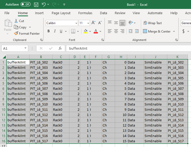
The I/O list specifies the input tag name as well as the Rack/Slot/Channel for each instrument in the field.
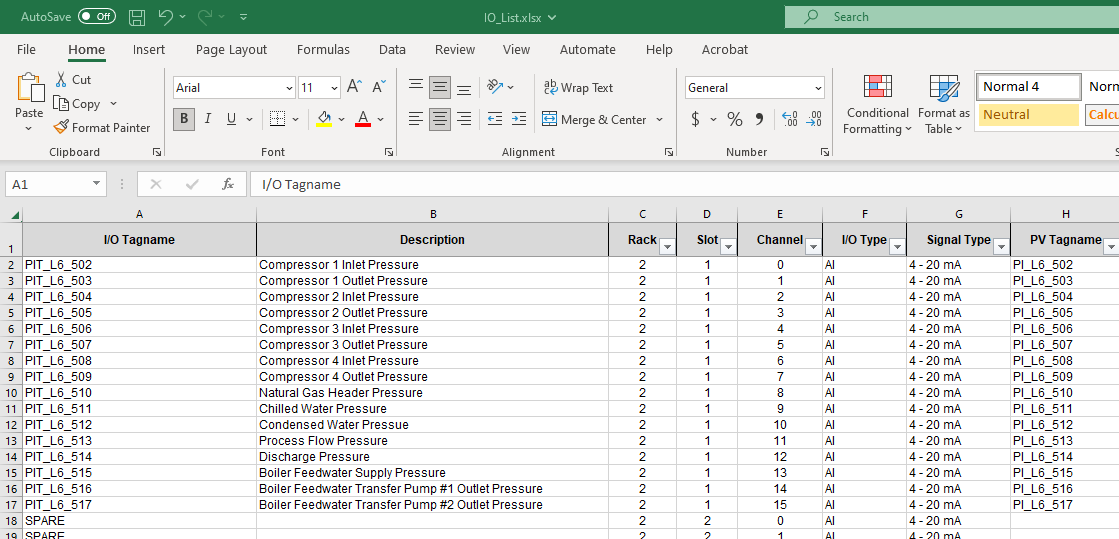
I have added an additional column (Column H) to our I/O list to account for an Alarm AOI block to which our scaled process value (or simulated process value) is passed. There is more on this alarm tag below. Our convention here at ACE is to include the “T” in the name of the buffering tag to indicate this value is from the field transmitter, while the internal process value tag ends in an “I” as this will contain our process variable that is indicated on the screen. With this convention in mind it is easy to use Excel’s Substitute() function or the copy and replace menu options to quickly create the data for this column using the I/O Tagname data as a basis.
Create the First Rung
We will begin by manually creating the first rung of the I/O mapping routine—in this case, the I/O mapping of Compressor 1 Inlet Pressure transmitter, shown below— and then double click on the rung number to reveal the underlying ASCII text for that rung of code. This will be the code that we use to base the rest of the mass-produced ladder logic from.
As shown in the screenshot below, the text reads:
“bufferAIInt PIT_L6_502 Rack02:1:I.Ch0Data SimEnable PI_L6_502”
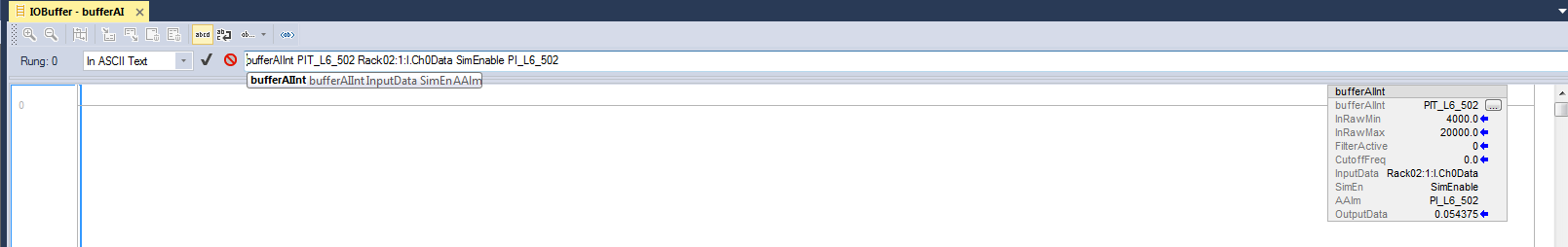
In this example, the syntax gives Add-On Instruction (AOI) and its associated arguments.
| Text | Description |
| bufferAIInt | AOI for Analog Input I/O Mapping |
| PIT_L6_502 | AOI instance name |
| Rack02:1:I.Ch0Data | Rack/Slot/Channel for instrument wiring |
| SimEnable | Enable/Disable bit for bench simulation |
| PI_L6_502* | Tagname of the PLC Alarm AOI consumes the scaled value and processes the analog alarms (i.e. High High) |
*The Alarm AOIs are processed in another routine and only referenced by the block shown here. The code for creating alarms is also a good candidate for Excel generated code.
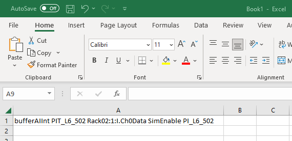
Copy and paste the text from Logix Designer into Excel.
Break the text into cells
The figure below shows what the rung looks like once it is copied into Excel. It is not very useful in this format.
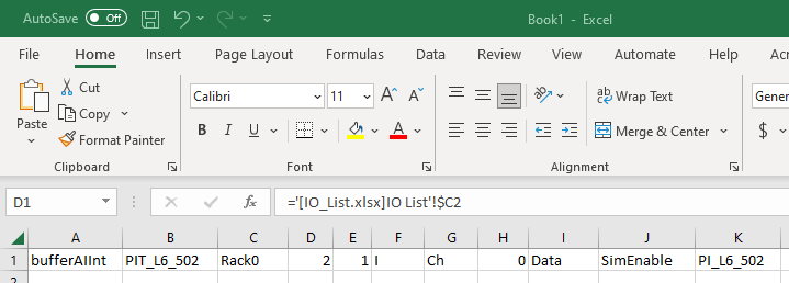
The Text to Columns Data Tool under Data menu can be used to quickly delimit the string. Using the tool in multiple iterations will allow us to separate the arguments (spaces) and the input locations (colons and periods). The result of this is shown in the figure below.
Create the New Rungs
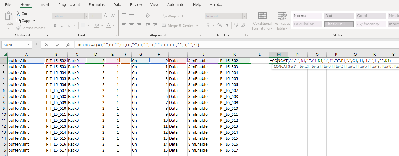
Now that our code is broken into the different components we can link the cells that represent rack number, slot number, channel number, and tag names to the corresponding cells in our I/O list. In the above diagram the Formula Bar is showing our reference to the rack number in our I/O list.
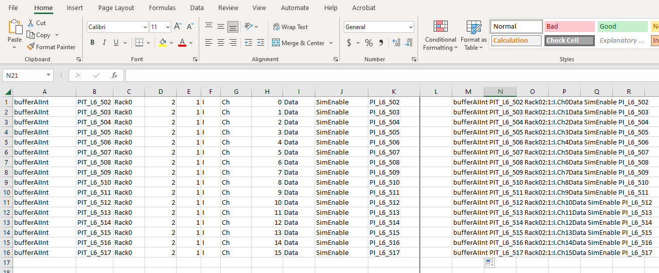
Once the references have been entered for each cell we can highlight the row of cells and drag the fill handle down the sheet to populate our sheet with our new rungs of code.
Now we use the Concatenate function in Excel to rebuild the data into a single string per row—remembering to add back in the delimiters, which were spaces, colons, and periods in this example.
Put the New Rungs into the Routine
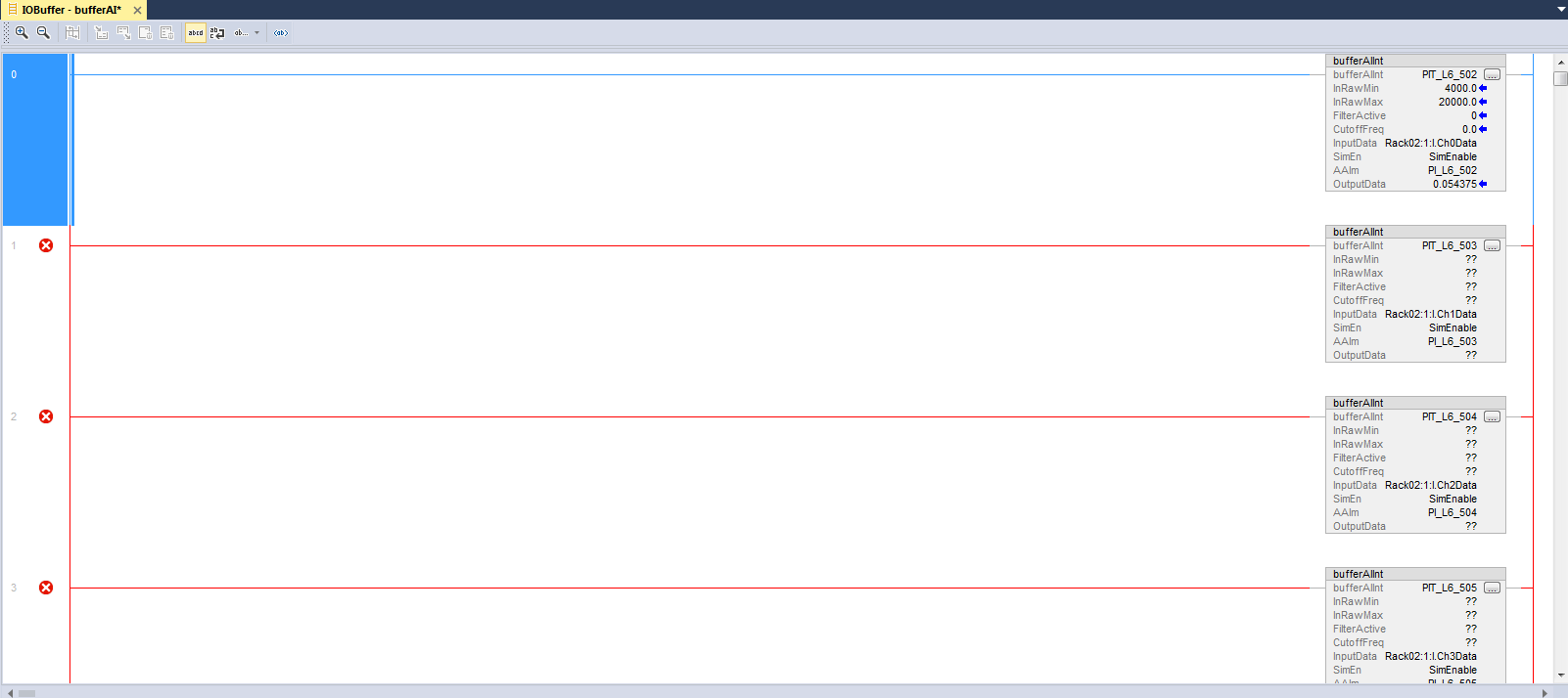
Now that we have a newly created string for each rung, we can copy the data from the cells directly into Logix Designer. Note that this can be done in bulk and does not need to be done cell-by-cell. Simply select all of the cells and copy the data. Then paste it into the ASCII text display we copied from earlier.
This will quickly add the I/O mappings as new rungs of code. If this is new code where the tags have not yet been created the new rungs will show in red as pictured below.
To remedy this, we will define the new tags using the I/O list and create an import CSV. Rockwell has documentation about their Import utility in their knowledgebase. In this case we used Excel formulas to create an import file that looks like the figure below.
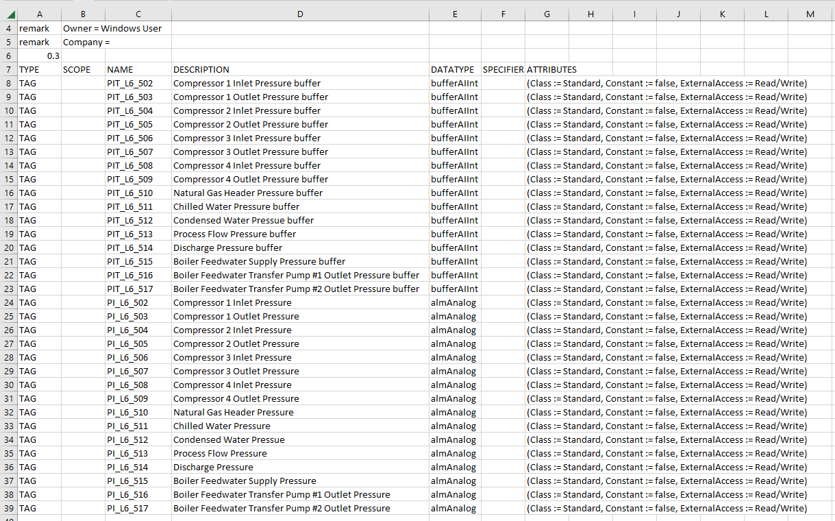
Importing this CSV file will resolve the errors and get rid of the red lines in our routine so that we can compile and test this code.
In conclusion, this is a really useful tool to save time when writing repetitive PLC code, such as I/O mapping and alarms. Please note that the amount of time saved is directly correlated to the size of the system you are working with (i.e. larger systems have more I/O). A method like this may not be useful for a smaller system. However, for larger systems the time and cost savings, not to mention the elimination of transcription errors, will make a big difference in a project.

Related Posts
How to Read & Write Rockwell PLC Tag Values with Excel
In the automation industry we are constantly looking for ways to improve our efficiency, streamline...
How to Communicate Modbus Natively with ControlLogix
The Modbus protocol was originally published in 1979 by Modicon as a simple request-response...
Maximize Productivity with Existing Equipment and Employees
It’s clear that if there was a way to increase productivity and data reliability without performing...